- In part 1, we examined the architecture of the Arduino and AVR microcontroller.
- In part 2, we set up the AVR-GCC toolchain and avrdude.
The Plan
This time, we will look at some more project-specific hardware buildup for a gradual-wake light clock.
This is meant to be at the “completely new to electronics design” level. If you know your way around parallel LEDs, you can probably build something better than I’ll build here.
Our Goal
Our regular alarm clock is pretty jarring, and it doesn’t really solve the problem of the room still being dark. How about we solve both of those at once by gradually lighting up the room?
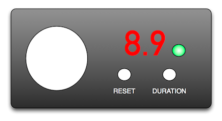
Obviously the real thing will be nowhere near as pretty, but it gives us an idea of what hardware and software components we will need:
- Timer – This will mostly be taken care of in software.
- Bright light – We will use a bunch of LEDs (preferably white)
- Time Display – We will display time until wake in hours + tenths of an hour
- Digit Display Library – some kind of abstraction for display numbers
- Status Light – Is the alarm on or off? (green = on, red = off)
- Reset – turn it off.
- Duration – increase the duration until wake within a set range, at the top it will simply loop back to the lowest value.
- Holding the reset button and pressing the duration button will turn the alarm back on after it has been turned off.
the light module
We’ll start with the simplest part first: making a bright light. We’ll use a tiny breadboard, but perhaps if I had more LEDs I could fill a half-size breadboard and outshine the surface of the sun. If you’ve never worked with them or are a bit rusty on the details of the various kinds of breadboards, have a look at the Wikipedia Article.
So, with a bunch of LEDs in one hand and the breadboard in the other, we want to know whether a series or parallel circuit will be the brightest. For reasons you can find out in second-semester college physics (or through empirical observation), the parallel configuration will give us the most light.
light module schematic
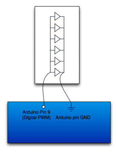
I may be really unclever, but my plan was to plant the LEDs straddling the breadboard. Then, to establish the parallel bus, rather than connecting each LED to the one physically next to it, stagger the connections. (I don’t have any physical jumpers that are pre-cut to span adjacent pins.)
assembly – light module
This is a bit tough to describe in words, but luckily I have pictures instead!
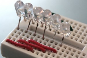
- Insert LEDs such that the pins are inserted into the innermost (nearest the gap) points. IMPORTANT: make sure all of the anodes and cathodes are on the corresponding side of the gap. I skipped one row between each LED using 5mm dome LEDs.
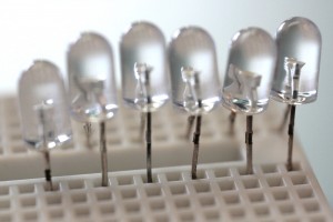
Pretty LEDs All In A Row. Notice the skipped rows. 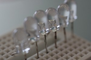
Pretty LEDs All In A Row, Part Deux: If you look closely at the inside of the LEDs, you can see the anode/cathode structure. - Parallelize 3 sets of LEDs.
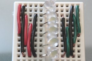
- You’ll need 3 jumpers of the same length. In my case, I chose to make them span 7 pins – the distance between 3 LED anodes/cathodes. And of course, I chose red for the anodic side and green for the cathodic side.
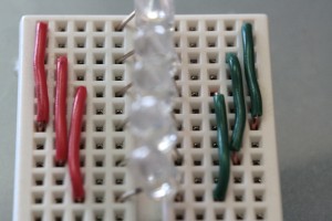
Top view. Parallel circuits for LEDs 1/4, 2/5, and 3/6 on the anode (left) and cathode (right) side. - Connect each set back to a bus row. Basically, we need each pair to connect back to one row, where we will actually connect the power and ground. Since there are only 4 columns available on my tiny board, some overlap was necessary. I used black wire to indicate bus connection wires.
- (optional) I chose to drag the bus down to the end of the board. The giant blur in the foreground is another larger white LED I had sitting around.
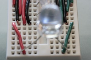
Two wires pull the bus down to the last row. Out of focus: giant LED.
- You’ll need 3 jumpers of the same length. In my case, I chose to make them span 7 pins – the distance between 3 LED anodes/cathodes. And of course, I chose red for the anodic side and green for the cathodic side.
Yay, we’re done building the light module!
quick test
For our first run, we’ll actually try a failsafe way to test rather than loading up any software.
For our positive voltage, connect a jumper from the anodic (red) side bus row to the 3V3 pin towards the “bottom” of the Arduino. Connect a jumper from the cathodic (green) side bus row to one of the two nearby GND pins on the Arduino. Now, connect the Arduino to its power source – probably USB. All of the lamps should glow brightly – if a single lamp is out, you probably have the anode and cathode reversed; switching its orientation on the breadboard should fix it.
The 3V3 pin is meant as a reference voltage pin, so we probably don’t want to test its capacity by leaving the lights attached for too long – disconnect your power source first, then the light module.
fancier test: dimming
We want to be able to raise the light level of the light from nothing to bright over some amount of time. For now, we’ll just focus on fading from dark to bright.
This part is easiest done with the actual Arduino toolkit: it contains an example sketch that does exactly that – raise and lower the output voltage of Digital PWM Pin 9. To load the sketch, we’ll leave the light module disconnected and open the Arduino software and open the Fading sketch from the File menu as shown:
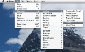
Once you have opened the Fading sketch, connect your Arduino to your computer (generally using USB), select the appropriate USB port in the Tools -> Serial Port menu, and click the “Upload” button highlighted below:
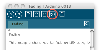
Once the RX and TX lights have stopped blinking and the software proclaims “Done uploading,” disconnect your Arduino from USB before we reattach the light module.
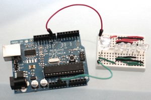
You can connect the cathodic side your light module to a GND pin on the bottom of the Arduino, or choose the one to the left of digital pin 13. The anodic side should be connected to our voltage source – Digital PWM Pin 9.
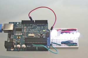
With both sides connected, you should now be able to reconnect your Arduino to a power source (USB) and see your many lights fading calmly.
the display module
Now that we have a light to light up, we need a way to show what duration remains before the “light alarm” goes off and whether or not the alarm is on.
Our digit display is clearly going to be two seven-segment LED displays; I’m using ones I picked up from the UNL EE shop – part number LSD5051, common cathode. The status light I chose is a combo RGB LED similar to this one. Be sure to notice that the forward voltages are not symmetric: while blue and green can handle 3.2V, red can only handle 2.0V and will burn up in a hurry if you’re not careful.
a new friend: the multiplexer
You may have noticed that there are a lot more pins coming off these display devices than we have left on our Arduino. Because LEDs are not instant on-off devices (though they’re darn close on a human time scale), we can use persistence of vision to our advantage and drive many more pins through a device called a multiplexer.
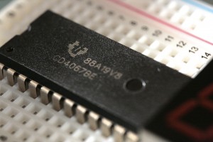
In particular, I’m using the TI CD4067BE. That part may be a bit hard to find, but fortunately, it’s available cheaply online. If you have to wait on it, you can check out its datasheet and get some idea of how it works. We’ll dive deeper into that next time.
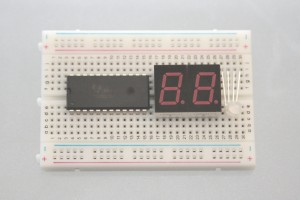
Once you have those parts, you can assemble a display module on a half-size breadboard that looks something like this one:
